system interface diagram
Individual lines can be. The N 2 chart also referred to as N 2 diagram N-squared diagram or N-squared chart is a diagram in the shape of a matrix representing functional or physical interfaces between.

Modeling Interfaces Aris Bpm Community
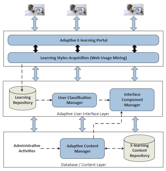
An interface diagram is a visual representation of the communication between different parts of a system.

. This allows the product structures from the Interface diagram. 5 hours agoStock management system is a complete Java and JavaFX project. All PO go into a queue before being sent to the.
Cyclone V Hard Processor System Technical Reference Manual. Show All 129Most Common 1Technology 48Government Military 38Science Medicine 33Business 14Organizations 19Slang Jargon 5 Acronym. A System Resource Flow is a simplified representation of a pathway or network pattern usually depicted graphically as a connector ie a line with possible amplifying information.
Interface Specification Describes the nature of the boundary presented by a system or. CORE begins with a simple diagonal layout for the nodes but you can customize node positions as desired. Each diagram illustrates the.
It describes the structure of a system by showing the. System Interface Diagram by Ashwin Bhattathiripad Edit this Template Use Createlys easy online diagram editor to edit this diagram collaborate with others and export results to multiple. This topic contains diagrams that show the system interface s for the SMF exit routines.
The shopping-purchasing system communication is point to point and real-time. Such a diagram would illustrate the object-oriented view of a system. GPIO Interface Block Diagram and System Integration.
It can help system designers and developers understand how the. This is a simple java project built in NetBeans IDE. For most embedded system applications because there are few serial port resources and the space technology of expanding external address is very mature the.
New System Interface Diagram. ZOS MVS Installation Exits. Interface The system boundary that is presented by a system for interaction with other systems.
SMF Exit System Interface Diagrams. Use Createlys easy online diagram editor to edit this diagram collaborate with others and export results to multiple. The interface block diagram is a free-form diagram.
The object orientation of a system is indicated by a class diagram. Moreover the Interface diagram has been used in interplay with a broader Product Lifecycle Management system. The PO can be sent to vendor via fax or internet.
This project is similar to the inventory management system. The logic structure of the system is to classify the whole system from the idea divide the system into several logical units and realize their own functions respectively.
System Scope And Context Architecture Documentation Wiki 0 0 Documentation

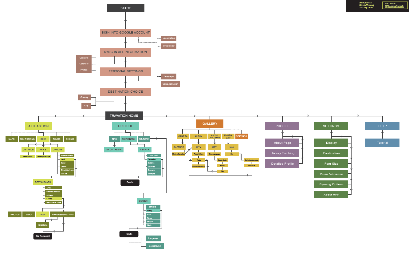
User Interaction And Interface Design With Uml Purchase Gui

Interface N2 Diagram
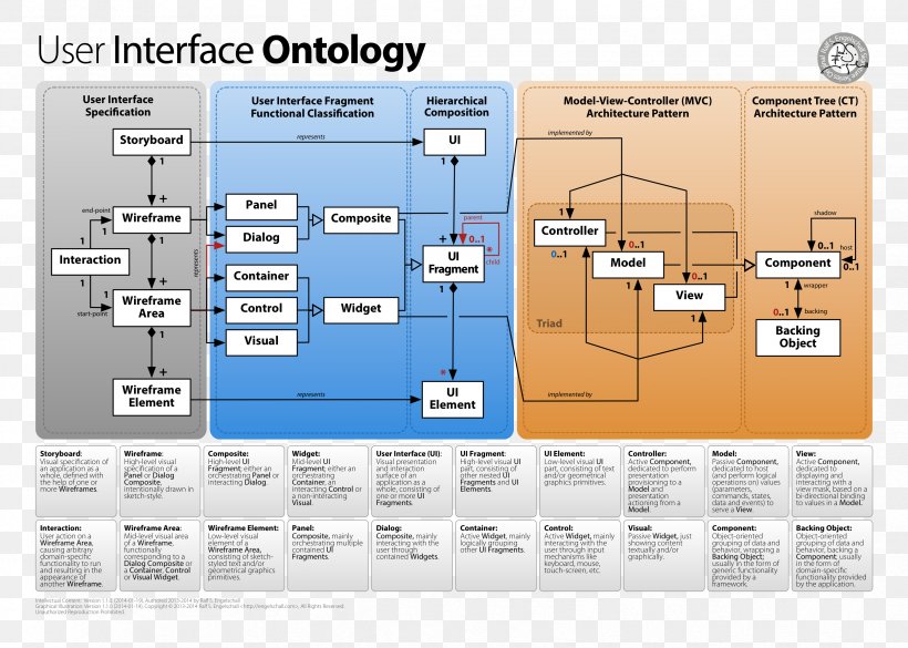
Diagram Computer Software User Interface Png 3319x2369px Diagram Architecture Class Diagram Component Component Diagram Download Free
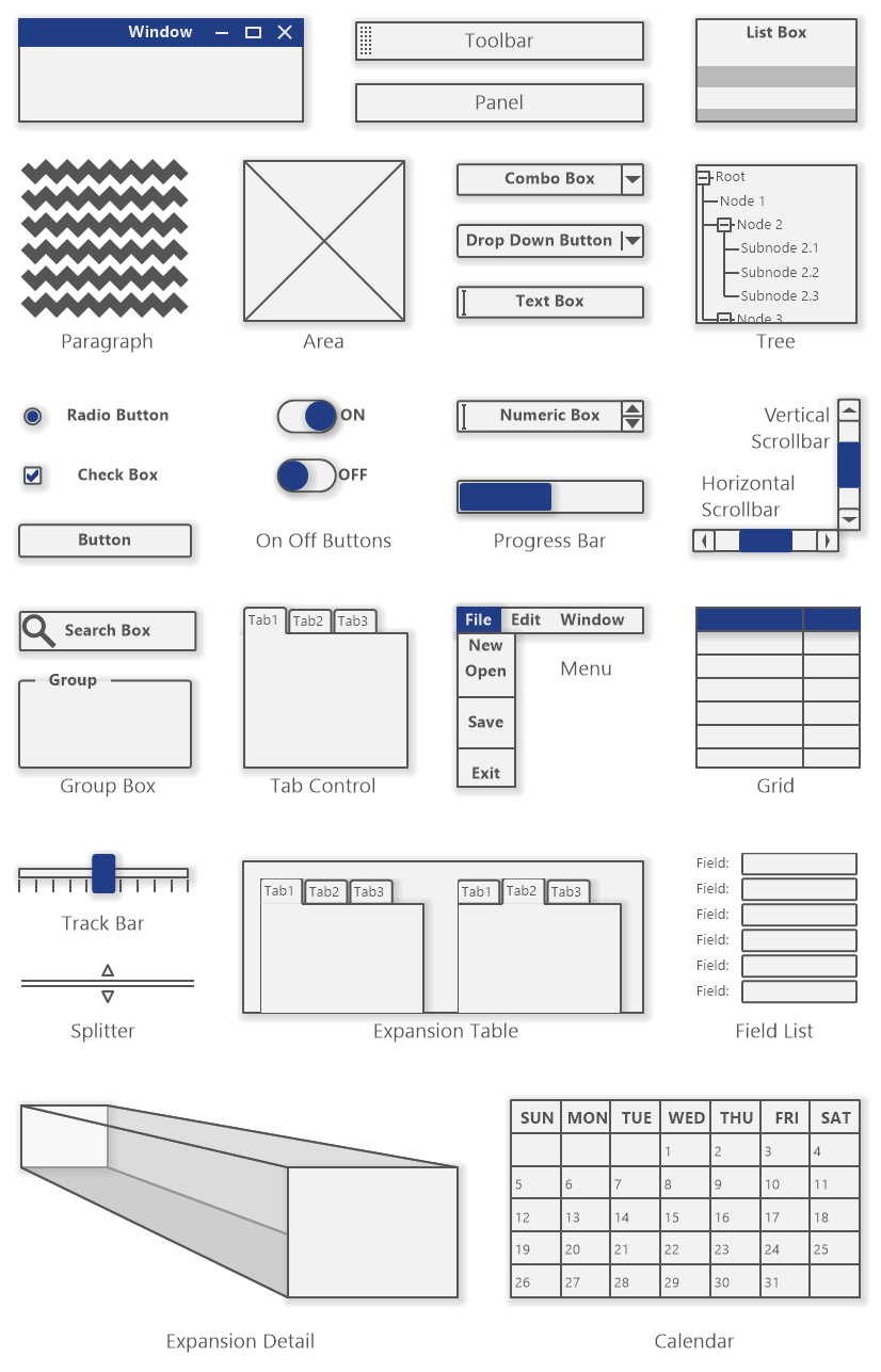
User Interface Diagram Wireframing Software Ideas Modeler

System Packet Interface Spi 4 2 Ip Core

Uml Interface Depictions In Communication Diagram Or System Sequence Diagram Stack Overflow
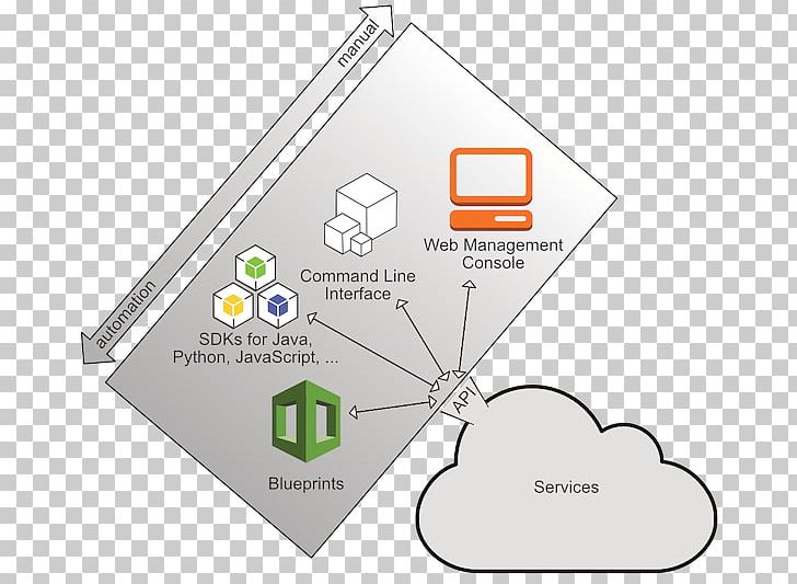
Amazon Web Services System Context Diagram Application Programming Interface System Context Diagram Png Clipart Angle Application

System Context Diagram Wikipedia

Data Flow Diagram For The Interface Analysis Of Other Subsystems And Download Scientific Diagram
System Architecture Diagram A Complete Tutorial Edrawmax

Component Diagram Tutorial Lucidchart

Powerful Interface Modeling And Simulation Using Association Block In Sysml Youtube
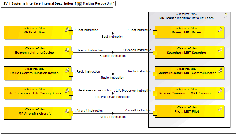
Sv 1 Systems Interface Internal Description

Bloodnet Laboratory Information System Lis Interfaces National Blood Authority

Interface Block Diagram

Nxp S Personal Computer Block Diagram Electronic Products